Abstract
Particle accelerators, originally developed to address fundamental questions about the universe, have become essential to various scientific disciplines. The broad adoption of accelerators was enabled by substantial advancements in beam manipulation techniques, which encompass methods for generating and controlling particle beams to optimize them for specific applications. Most of these manipulations rely on controlling the beam’s correlation in its phase space. While linear control and the correction of low-order nonlinearities have propelled particle accelerators to their current state, the exploration of more advanced control methods may provide new opportunities to achieve unprecedented beam qualities and conditions. Consequently, there is an increasing demand for control over higher-order nonlinearities. A recently developed method utilizing transverse wigglers shows potential in addressing such demands. Active research is also ongoing on diverse applications of the transverse wiggler-based method in various accelerator fields. This paper discusses methods for controlling highly nonlinear correlations and their applications.
1 Introduction
A particle accelerator is a facility that generates a desired particle beam, accelerates it to the required energy, and delivers it for applications across various areas of scientific research. The advancement of accelerators has always been driven by progress in addressing three fundamental questions related to the three major functions of the accelerator: how to generate bright beams, how to achieve higher energy, and how to control and optimize the beam for different applications. This is why beam manipulation, defined as the set of activities involved in controlling and optimizing the beam for the accelerator system and applications, is particularly important. It plays a critical role in making significant advances toward next generation accelerators as it addresses all three of these fundamental questions.
Examples of this can be found throughout the history of accelerators. Circular accelerators began with the simple cyclotron [1], which adopted weak focusing from dipole magnets, and evolved into modern storage rings through the development of quadrupole magnets [2], which provide strong transverse focusing on the beam (i.e., beam confinement in a smaller cross-section). Continued advancements in beam confinement and control methods have, in turn, pushed the brightness of beams to near diffraction-limited levels in recent years [3]. Similarly, the principle of introducing a path length difference for particles based on their energy led to the concept of magnetic bunch compression. This beam manipulation became a game-changer in the late 1990s and enabled the realization of a new type of light sources, the X-ray free electron lasers (XFEL) [4].
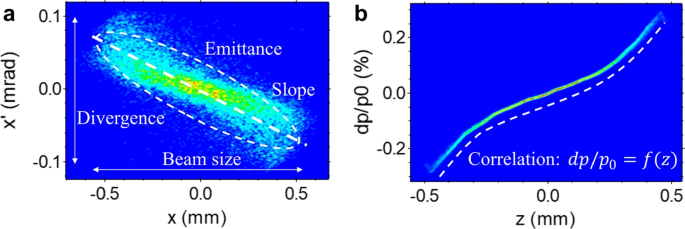
Beam manipulations in modern accelerators can be categorized into two types. One involves methods that directly control the beam’s density distribution in the phase space while the second focuses on controlling correlations between phase space. Note that the particle beam is a collection of particles that are close to each other and share similar properties. As a result, the particle distribution in phase space exhibits specific patterns as shown in Fig. 1. Density controls are relatively specialized and include only a few specific manipulations such as cooling [5], repartitioning [6, 7], and exchange [8, 9]. Most other existing beam manipulations fall under correlation control.
It is clear that correlation control is a critical factor in advancing accelerators. Various methods have been proposed, tested, and adopted. However, most efforts have focused either on controlling linear correlations for applications such as transverse or longitudinal focusing and removing nonlinear components from correlations, a process known as linearization. This linearization process has been limited to low-complexity correlations. While the typical accelerator components, such as RF cavities and static electromagnets, introduce low-order complexity in the particle beam’s phase space, collective effects from self-generated fields such as space-charge forces and coherent synchrotron radiation (CSR) can introduce much more complex correlations. Thus, although existing methods and approaches are sufficient for modern accelerators, their limitations are becoming increasingly apparent.
Recent research revealed new opportunities enabled by more advanced beam manipulations such as attosecond X-ray pulses [10], nonperturbative QED study with beam-beam collision [11], and high-efficiency wakefield acceleration [12, 13]. There is no doubt that introducing designed nonlinearity into the phase space or eliminating highly complex nonlinearity could open new opportunities and significantly enhance the performance of existing facilities. Therefore, addressing how to impart and eliminate designed nonlinearity will be the one of the major challenges for the next generation accelerators [14].
This paper reviews efforts to impart and eliminate nonlinearity in the phase space. Several methods and tools have been proposed and experimentally demonstrated. We begin with a discussion of methods that control low-complexity nonlinearity. The remainder of the paper discusses recent efforts toward arbitrary correlation and highlights a few applications. Note that we focus on unconventional methods, and this is not an exhaustive list of developed or developing methods. References [15] and [16] cover a broader range of beam manipulation methods. Additionally, while existing higher-order optics, such as magnet pole shaping or placing multi-pole magnets along the beamline, address similar issues, these approaches mostly focus on beamline optics rather than the beam’s phase space. Since different perspectives and interests lead to different outcomes, we limit our discussion to methods aimed at making instantaneous changes to the beam’s phase space correlation.
2 General principle of correlation control
Beam control generally occurs in three steps: applying electromagnetic fields, updating the particles’ momentum due to the fields, and updating the particles’ position based on the updated momenta. When there is no cross-plane coupling, the particle’s motion in each plane can be considered separately. In this case, the position update depends solely on the duration of the beam drift. Consequently, efforts to develop or improve beam manipulation methods focus on generating the desired electromagnetic fields.
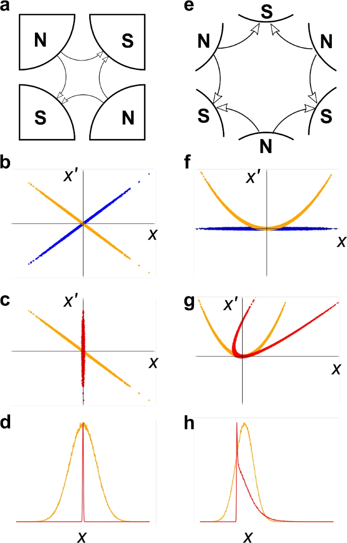
For example, if the application requires a small beam size, transverse focusing can be achieved using a quadrupole magnet. A quadrupole magnet (see Fig. 2a) introduces magnetic field near the beam moving axis as,
where \(G_q\equiv B_r/r_0\) is the field gradient, \(B_r\) is the field at the pole tip, and \(r_0\) is the bore radius. This field introduces a linear force on the beam. Particles experience horizontal and vertical forces (with the sign depending on the sign of \(G_q\) and the particle type) that are linear with their horizontal and vertical positions relative to the quadrupole, respectively. As a result, particles’ momentum will be updated as shown in Fig. 2b. The beam drifts with this updated momentum as shown in Fig. 2c. The beam size in x-direction (\(\sigma _x\equiv \sqrt{\left
Quadrupole and sextupole magnets and their impact on phase space. Each column corresponds to cases involving quadrupole or sextupole magnets. Each row presents the following in order: geometry, momentum update by the magnet, position update by subsequent drift, and the corresponding 1D-profile change. Blue, orange, and red colors represent the transverse phase space before the magnet, after the magnet, and after the drift following the magnet
On the other hand, linear controls on one of the x, y, or z planes only change the weight between the corresponding spatial and momentum distributions, which usually do not noticeably alter the beam’s one-dimensional profile (see panel d). If we replace the quadrupole magnet with a sextupole magnet shown in Fig. 2e, it introduces the following field near the axis,
where \(G_s\equiv B_r/{r_0}^2\). If the beam is focused vertically and has a negligible vertical beam size through the sextupole magnet, the horizontal force introduced by the sextupole magnet is quadratic with respect to particles’ horizontal positions. Thus, it changes the originally linear correlation to a quadratic correlation; see panel f. When the beam drifts, the correlation changes as shown in Fig. 2g. The most important difference between the correlations in panels c and g is their projected profiles. If the original x-profile and x’-profile was Gaussian, Fig. 2c, which experienced linear control, retains the same profile but scaled. However, Fig. 2g will result in a triangular profile, as shown in the panel h, due to the nonlinearity introduced in the correlation.
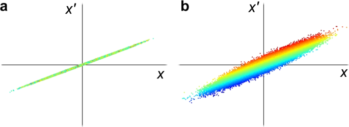
Contrary to the previous example, control over a single plane may not be available due to a lack of equipment or other practical limitations. An alternative approach to overcome this issue is to introduce coupling between the coordinate of interest and a more easily controllable coordinate. In this way, the field applied to the easily controllable coordinate will also affect the coordinate of interest. However, it is important to note that all introduced couplings must be eliminated after manipulation as cross-plane coupling increases the phase space area of each plane, known as projected emittance; see Fig. 3. The emittance (\(\varepsilon\)) is a measure of beam quality (e.g., brightness \(\sim 1/\varepsilon\)), and an increase in emittance can lead to a significant performance degradation of accelerator applications.
Impact of cross-coupling on 2D phase space. a shows nominal phase space without coupling with longitudinal momentum. b shows a phase space having coupling with longitudinal momentum. The color corresponds to the particles’ longitudinal momentum. Red and blue represent higher and lower momentum, respectively
3 Controls in low-complexity nonlinearity
3.1 Transverse control
Among the various equipment providing electromagnetic fields, static electromagnets or permanent magnets are commonly used for transverse beam control due to their straightforward implementation and simple control. In general, the magnetic field generated by magnets can be expressed as (for normal n-poles) [17],
This field generated by n-pole magnets can shape the phase space correlation. Most linear correlation controls can be achieved by a quadrupole magnet (\(n=2\)), which provides stretch and shear along the momentum-coordinate, and drift leading to shear along the position-coordinate. On the other hand, nonlinear controls typically use higher-order (\(n>2\)) magnets such as sextupole and octupole magnets. A single magnet may be sufficient for certain applications, but a series of higher-order magnets can produce a magnetic field in polynomial form. If the desired correlation can be approximated by a polynomial series, the series of higher-order magnets will be able to generate it.
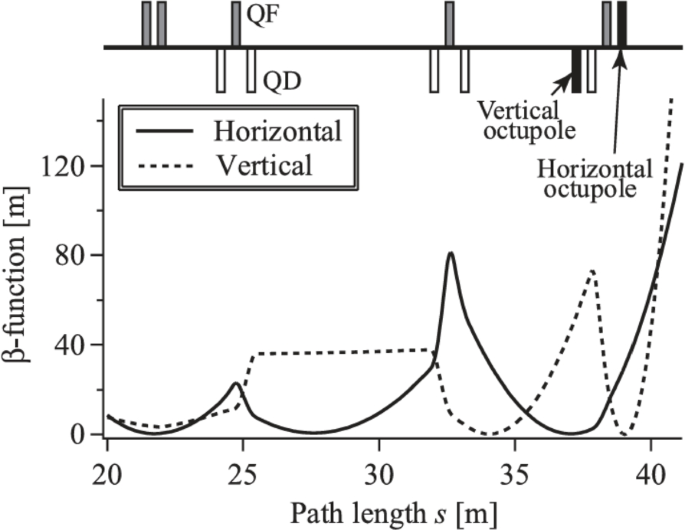
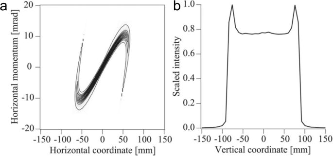
Homogenization using an octupole magnet is a good example, which is often employed in beam expander [18]. Heat control is a major concern for applications requiring a high-power beam to hit a target. To reduce heat density, a uniform and large beam size at the target is preferred. Such a beam is typically achieved using two sets of quadrupole and octupole pairs. As illustrated in Fig. 4, for example, the first quadrupole magnet focuses the beam in the x-plane at the location of the first octupole. At this point, the octupole magnet’s field components is ignorable except for \(y^3\)-term that introduces folding in Fig. 5. After this octupole, the beam size in the x-direction begins to diverge. The second quadrupole focuses the beam in the y-plane at the location of the second octupole, where a similar process occurs in both the x- and y-planes.
Beam envelope along an expander. From Ref. [19]
Simulated horizontal phase space and vertical profile downstream of an expander. Adapted from Ref. [19]
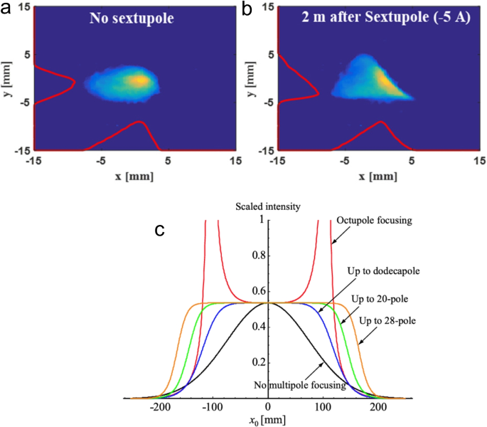
Similarly, other higher-order magnets can be used for similar purposes. Odd-order magnets introduce correlations with point symmetry that leads symmetric profile changes while even-order magnets generate correlations that are symmetric with respect to the momentum axis, producing asymmetric profiles as shown in Fig. 6. Reference [19] demonstrated the feasibility of improving uniformity using a dodecapole magnet or even higher-order magnets in simulation. Reference [20] presented an experimental demonstration of the profile conversion to a triangular profile using a sextupole magnet. Note that such triangular profiles in longitudinal plane can enhance the efficiency of wakefield accelerators beyond the theoretical limits imposed by the fundamental theorem of wakefields [12, 13, 21, 22].
Examples of nonlinear shaping. a and b show experimental data for the generation of a triangular profile in the vertical direction. Each panel presents electron beam image measured without and with sextupole focusing, respectively. c demonstrates the generation of a uniform profile. It displays simulated profiles using various even-order multipole magnets. Figures are adapted from Refs. [20] and [19]
3.2 Longitudinal control
While magnets control transverse correlations, longitudinal correlations are typically controlled by electric fields, which change the beam’s energy. The energy gain of a particle under an electric field can be expressed in general as follows:
where \(\Delta \mathcal {E}\) represents the changes in the particle’s energy, \(\bar{E}\) is the electromagnetic field, and \(\bar{v}\) and \(\bar{r}\) are the velocity and position of the particle, respectively. Various types of equipment generating electric fields, such as RF cavities, wakefields from high-impedance structure or plasma, and laser-beam interactions, have been adopted to control longitudinal correlations. These equipment often introduce oscillating sinusoidal fields. Thus, when the beam’s longitudinal size is comparable to or shorter than the wavelength (i.e., \(\sigma _z\le \lambda _E\)), the impact on the correlation can be approximated using a polynomial form, similar to the transverse case. On the other hand, fields with wavelengths much shorter than the bunch length will impart a sinusoidal modulation on the longitudinal phase space. This sinusoidal modulation imparted on the longitudinal phase space can serve as one of the frequency components in a Fourier approximation of correlations, which can handle much more complex nonlinearities.
3.2.1 RF cavity
A linear slope of the longitudinal correlation, called chirp, is usually adjusted by operating accelerating cavities to off-crest phase. The energy gain from an accelerating cavity can be simplified to \(eV \cos {\left( \omega t + \phi \right) }\) where V is the effective accelerating voltage applied to the cavity, \(\omega\) is the angular frequency, and \(\phi\) is the phase offset. For conventional acceleration, bunch length is much smaller than the wavelength of the accelerating RF field. Thus, the energy gain of the particle beam can be approximated as,
It is clear that the phase offset controls the chirp, but it also affects the overall energy gain and impacts the second order correlation. When the phase is close to 90°, the accelerating cavity provides almost linear correlation, but the energy gain becomes zero.
Linac phase control is the most popular method because all accelerator facilities are equipped with accelerating cavities. However, we can consider a new concept designed solely for linear control purposes [23], which can more efficiently control the linear correlation. This method uses transverse deflecting cavities (TDC) as the main tool for controlling the correlation. At the zero-crossing phase with assumption of a kick in the x-plane, this cavity introduces an \(E_z\)-field whose strength is proportional to particles’ x-position and \(B_y\)-field whose strength is proportional to particles’ z-position (arrival time compared to the zero-crossing phase). Thus, the beam passing through the first TDC receives a transverse kick based on its longitudinal position (see Fig. 7a). This introduces coupling between x and z, so the \(E_z\) field in the second cavity accelerates or decelerates the beam based on its horizontal position. Due to the coupling introduced by the first cavity, the longitudinal correlation changes at this point. The remaining sections of the beamline eliminate the couplings introduced by the first cavity. A simulation result demonstrating this linear control is presented in Fig. 7b.
Conceptual drawing illustrating the principle of a deflecting-cavity-based chirper and its simulation results. a is a schematic drawing depicting the chirping process, where color represents the beam’s energy—red indicates higher energy. b shows simulated longitudinal phase spaces at three different locations: blue represents the phase space at the entrance, while red and green correspond to the phase spaces at the exit of the chirper with 0 pC and 100 pC charge, respectively. Adapted from Ref. [23]
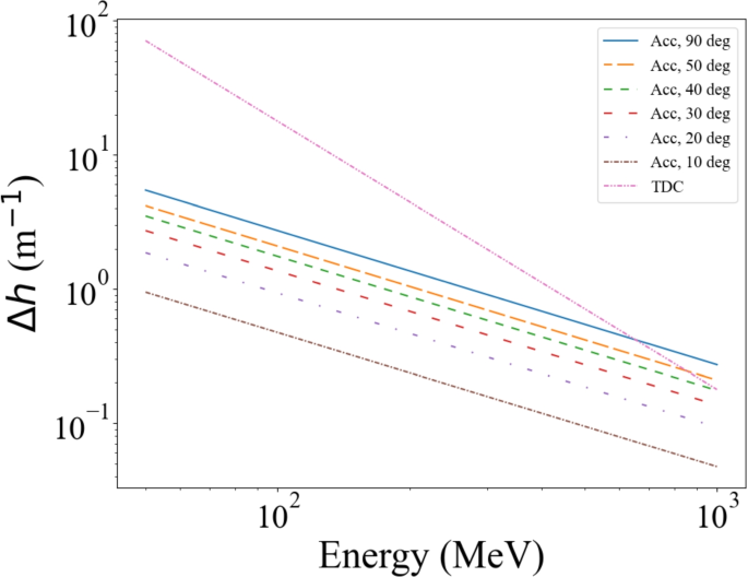
Assuming L-band accelerating cavities [24] and TDCs [25], the energy change that the accelerating cavity can impart is \(eV\omega \sin {\phi } \Delta t\) while the TDC chirper can achieve an energy change of \({2\over 3}\kappa ^2\left( 3D+2L_c\right) E_{avg}\) where \(\kappa \equiv {eV_\perp \over E}{2\pi \over \lambda }\). If a voltage of 10 MV is applied to the accelerating cavity and 5 MV to the first TDC, along with appropriate voltage to the other TDCs, the TDC-based chirper can introduce a greater changes in the chirp than the accelerating cavity (see Fig. 8). Note that D is assumed to be 1 m and \(L_c\) to be 0.3 m. The changes in the chirp of high-energy beams can also be enhanced by adjusting these factors. Thus, it is not an exaggeration to say that the TDC chirper is an efficient way to control the longitudinal chirp.
While the previous two examples focused on linear control, cavities can also control nonlinearities. In the case of off-crest phase operation for correlation control, the second-order components in Eq. 5 must be addressed to linearize the phase space. Since any accelerating cavities introduces fields like Eq. 5, introducing a second cavity can cancel out this second-order term. However, the elimination of the second-order term should not affect the zeroth-order term, which represents the energy gain, or the first-order term. Thus, it is necessary to increase the frequency of the second cavity and set the phase to −180°.
where subscripts a and l denote the accelerating cavity and the linearizing cavity, respectively. The second cavity with a higher frequency is typically referred to as a harmonic linearizer [26].
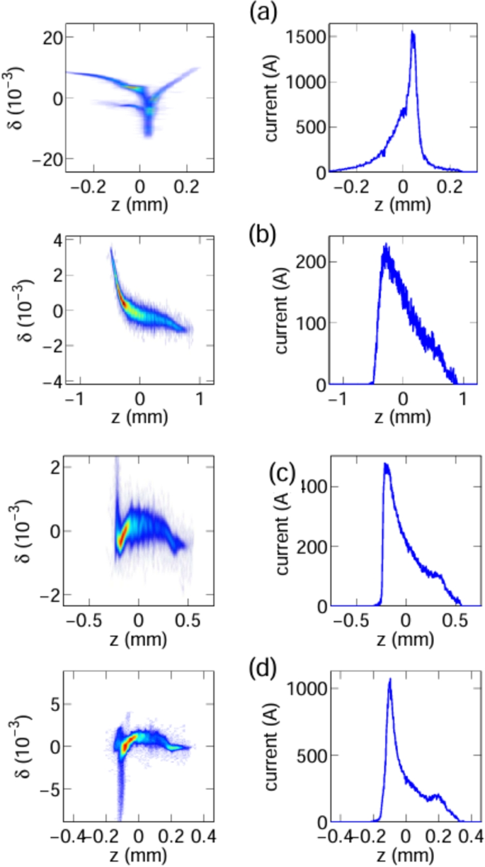
Using two or more cavities operating at different frequencies can generate further generalized correlations in the longitudinal phase space. Reference [27] controlled two accelerating modules operating at 1.3 GHz and 3.9 GHz separately. This additional degree of freedom enabled the generation of various longitudinal correlations as displayed in Fig. 9. The longituidnal position update by momentum slows down significantly as the beam energy increases due to relativistic effect. Thus, introducing an anisochronous beamline, like chicane, is necessary to update the particles’ z-position. When the beam passes through an anisochronous beamline, particles’ z-position are redistributed based on their original positions and the updated momentum from the accelerating modules. Specifically, in chicane, if the tail particles gain higher energy than the rest of the beam, they can overtake preceding particles and begin to form a density spike. Properly tuning the correlation using the two accelerating modules can generate asymmetric triangular profiles as shown in the right column of Fig. 9.
Measured longitudinal phase spaces and corresponding current profiles. Each row corresponds to a different accelerating voltage and phase combinations for the two accelerating modules used in the experiment. The values \((V_1,\phi _1,V_2,\phi _2)\) [in (MV, °, MV, °)] are (150.5, 6.1, 20.7, 3.8), (156.7, 3.8, 20.8, 168.2), (155.6, 3.6, 20.6, 166.7), and (156.8, 4.3, 20.7, 167.7) for case a–d, respectively. The figure is from Ref. [27]
While their experimental demonstration achieved a high-quality triangle current profile, it is important to note that the method operates under \(\lambda _{RF}\gg \sigma _z\) where the Taylor expansion is valid. Thus, this method will generate correlations approximated by polynomials. Adding more cavities with higher operating frequencies would help to extend its capability. However, a critical limitation of this method is the requirement for separately controlled RF power sources.
3.2.2 Wakefields
Two other mechanisms for controlling longitudinal correlation are wakefields and laser-beam interactions. Extensive summaries of methods and principles based on wakefield and laser-beam interaction are provided in Section V.C of Ref. [16] and Section III of Ref. [15]. Therefore, this section and the next will briefly discuss the basic ideas.
A wakefield is a retarded electromagnetic field generated by a charged particle beam interacting with a high-impedance medium or geometric variations in the medium’s boundary [28]. When there are abrupt changes in the boundary or when the boundary consists of high-impedance media, such as dielectric or plasma, the boundary slows down the propagation of electromagnetic field compared to the beam. This can be considered as the beam losing its energy due to high-impedance of the medium, which excites a voltage.
The energy change due to wakefield can be expressed as [29],
where Q is the total charge, \(\lambda (z)\) is the normalized longitudinal line-charge density, and w(z) is the wakefield generated by a single particle. The wakefield from a single particle can be represented as the summation of cosine waves with different frequencies and amplitudes.
where \(\kappa _i\) is the loss factor of the ith mode and \(k_i\) is the wave number of the ith mode.
When the wavelength of the wakefield is much longer than the bunch length, it introduces quasi-linear changes to the longitudinal correlation. Due to the energy loss nature of the wakefield, this chirp always causes the tail to lose more energy than the head. Conversely, when the wavelength of the wakefield is comparable or shorter than the bunch length, the wakefield can actively introduce nonlinear curvature in the longitudinal correlation. This nonlinear correlation around the tail can be used to shape the bunch’s current profile [30] or to linearize the longitudinal phase space [31]. Once the bunch length exceeds one wavelength of the wakefield, the wakefield can impart sinusoidal modulations, which can be employed for bunch train generation [32] or as a source of Fourier approximation for more generalized correlation control.
It is also worth to note that the wakefield generated by one bunch can be used to control another bunch [33]. In this case, the role of the wakefield is similar to that of RF cavities, except that wakefields for this purpose typically operate at much higher frequencies (10–1000 GHz) compared to RF accelerating cavities (1–10 GHz).
While the wakefields are an interesting tool for controlling correlations, it has several notable limitations. For single-bunch control, the field pattern is defined by the current profile, which is not straightforward to manipulate. Additionally, the amplitude tuning range is quite limited once the operating frequency and bunch charge are chosen. In the case of two bunches, the amplitude and period of the sinusoidal field from a preceding bunch are not easily adjustable. As a result, applying multiple designed modulations to adjust the correlation becomes challenging. Furthermore, when two bunches move along the same axis, it introduces significant difficulties in transverse beam transport.
3.2.3 Laser-beam interaction
The laser-beam interaction is well reviewed in Ref. [15]. This section will again briefly discuss the basic idea.
A laser pulse is an electromagnetic field propagating through free space. While the interaction of any electromagnetic field with a charged particle introduces the possibility of energy gain (see Eq. 4), laser-beam interaction in free space cannot provide a net energy gain to the particle, which is known as general acceleration theorem [34]. Therefore, as RF cavities use irises to slow down the wave for effective interaction with the beam, laser-beam interactions also require additional tools to achieve a non-zero energy gain.
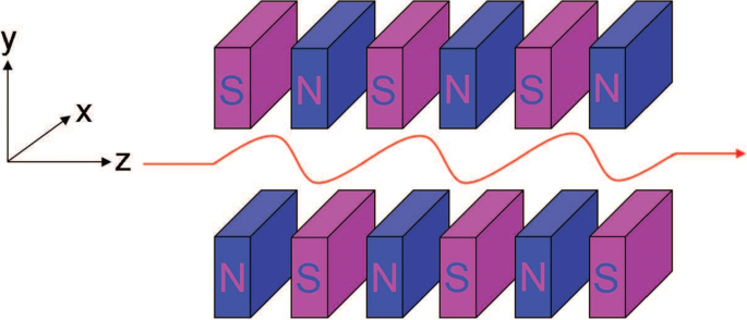
This interaction can be accomplished by placing the laser-beam interaction within the magnetic field generated by a wiggler. The wiggler is two Halbach arrays producing alternating transverse magnetic fields, which can be expressed as [35],
where \(k_w={2\pi \over \lambda _w}\), \(w_m\) is the width of the magnet, and h is the height of the magnet. Assuming \(\gamma \gg 1\), this alternating magnetic field causes the beam to drift with wiggling motion (see Fig. 10). During this motion, the transverse and longitudinal velocities can be written as [15],
where \(\beta _{x,z}\) are the relativistic beta for x- and z-directions, and \(K = {eB_0\over k_w mc^2}\). The first two terms of \(\beta _z\) is equal to the average speed of the beam over one wiggler period. It indicates that there will be a relative delay of the electron beam for each wiggler period. This distance, known as slippage, is given by \(\left( {1+K^2/2\over 2\gamma ^2} \right) \lambda _w\). When the laser’s wavelength matches the slippage, the laser-beam interaction continuously transfers energy. The energy change at the end of the wiggler can be expressed as [15],
where \(P_L\) is the laser power, \(P_0=I_A mc^2/e\approx 8.7\) GW, \(I_A\) is the Alfvén current, \(\mathcal {J}= J_0[K^2/(4+2K^2)]-J_1[K^2/(4+2K^2)]\), and \(w_0\) is the laser radius at the waist.
Wiggler and electron motion. The figure is from Ref. [15]
Contrary to the wakefield, the wavelength of a laser is typically much shorter than the bunches. As a result, laser-beam interactions generally aim to impart sinusoidal modulations on the longitudinal phase space, which are often converted to density modulations via a chicane, ultimately serving as a source of coherent radiation. The superposition of such controlled sinusoidal modulations offers significantly more flexibility for correlation generation compared to polynomial-based ones. One or two lasers can provide interesting controls on the phase space correlations like increasing uncorrelated energy spread to suppress microbunching instability [36], laser heater-based temporal shaping [37], and generating ladder like structure for strong harmonic radiation [38].
Although the sinusoidal nature of laser-beam interactions holds great potential for arbitrary correlation generation, integrating such a system is both expensive and space-consuming. Preparing and transporting lasers with multiple different frequencies to form harmonics of a Fourier series may not be practical.
4 Toward control over high-complexity nonlinearity
4.1 Fourier series and arbitrary cosine sum
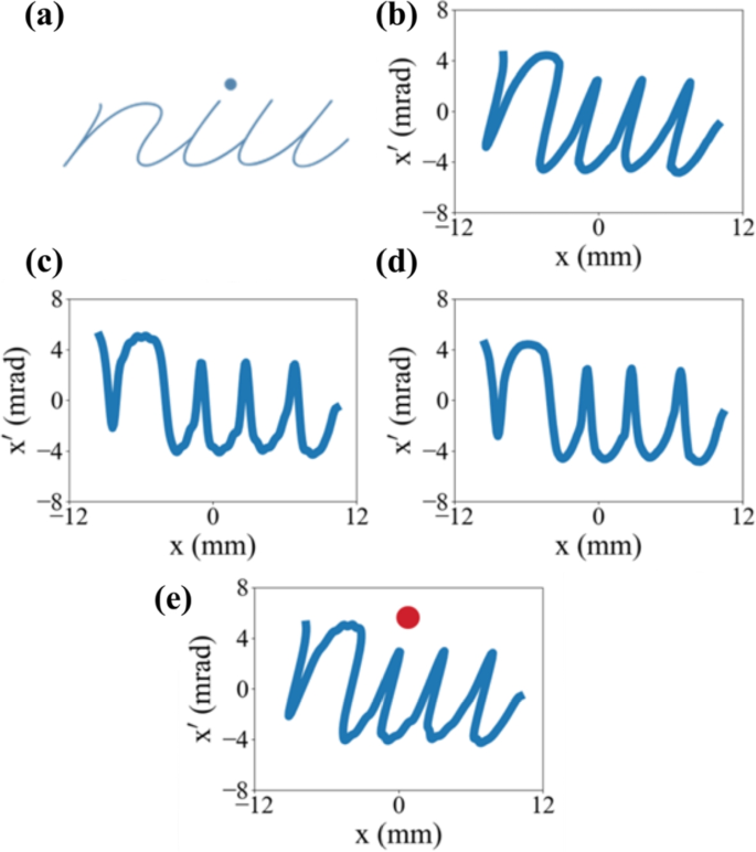
The methods introduced in the previous section either generated polynomial-approximated correlations or imparted one or two sinusoidal modulations and their superposition. While these methods serve important role and introduced new opportunities, they do not achieve fully generalized correlation control (i.e., arbitrary correlation). References [39, 40] proposed a method for producing correlations approximated by a Fourier series or a summation of arbitrary cosines. When a complex correlation, such as the one shown in Fig. 11a, is desired, it can be approximated using a Fourier series with a conversion of the target correlation into a function form (e.g., back-drift displayed in panels b and d). In the example in Fig. 11, the desired correlation (i.e., word “niu”) was approximated by a Fourier series with 70 harmonics. As the beam drifts, this correlation shears and can be matched to the originally desired shape shown in panel b.
A process generating desired correlation using Fourier series. a is a desired shape and b is corresponding desired correlation in the phase space. d is the phase space after reverse-drift. c is the correlation approximated by a Fourier series with 70 harmonics. e is the final correlation after the drift. The figure is from Ref. [40]
The idea of using the summation of cosines is particularly powerful for beam correlation control due to the finite size of the beam. It is well known that Fourier series can approximate any periodic function. Finite beam size enables the conversion of any desired correlation into a periodic function by mirroring it across the domain. Additionally, cosines with longer wavelengths (where \(\lambda>=\sigma _z\)) introduce polynomial components into the correlation. The summation of arbitrary cosines, rather than Fourier harmonics, allows approximation of a desired correlation as part of any function that matches locally. This approach extends far beyond what polynomials can achieve and provides control over high-complexity nonlinearities that were previously inaccessible.
As noted in Ref. [40], when the correlation exhibits periodicity, the summation of arbitrary cosine does not outperform the Fourier series. All variables in a Fourier series are analytically determined, whereas arbitrary cosine sums require optimization of variables to fit the correlation. Therefore, the Fourier series is preferred for periodic correlations. However, in cases without periodicity, arbitrary cosine sums typically require less terms to achieve the same quality of manipulation. Further research on efficient algorithms are necessary to optimize the design and fine-tine settings during operation.
4.2 Transverse wiggler
Several types of equipment provide cosine modulations (e.g., wakefield and laser). Since the approximation requires specific cosine modulations, the modulator must control three parameters: amplitude, phase, and period. However, it is not straightforward to control amplitude and phase of modulations from wakefields across successive modulators, as the wakefield source (the beam) has a fixed charge (see Eq. 7). While lasers can easily control both amplitude and phase, tuning their wavelength is more challenging.
Reference [41] proposed a new application for existing equipment. By rotating the wiggler introduced in Section 3 by 90°, it produces a sinusoidal vertical or horizontal magnetic field along the other transverse direction. This configuration allows a sufficiently wide beam passing through the wiggler to receive modulation in the horizontal or vertical phase space. Consequently, this finger-sized wiggler with the rotation is termed a transverse wiggler.
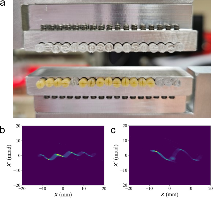
The transverse wiggler can control all three cosine parameters effectively. As indicated in Eq. 9, it adjusts modulation amplitude by changing the gap. The phase corresponds to the relative horizontal deviation between the beam center and the wiggler center. Initially, transverse wiggler were fabricated using permanent cube magnets, which fixed the period. However, in 2023, Reference [42] introduced a new type of transverse wiggler utilizing cylindrical magnets that allows rotatable magnetic polarization (see Fig. 12). This advancement enables the generation of modulations with tunable amplitude, period, and phase. It also produces more complex patterns without relying on the superposition of multiple transverse wigglers. Consequently, it is referred to as a reconfiggler.
Picture of reconfiggler and measured horizontal phase spaces. a is a picture of the reconfiggler. b and c show measured phase spaces with different settings of the reconfiggler. Figures are from Ref. [42]
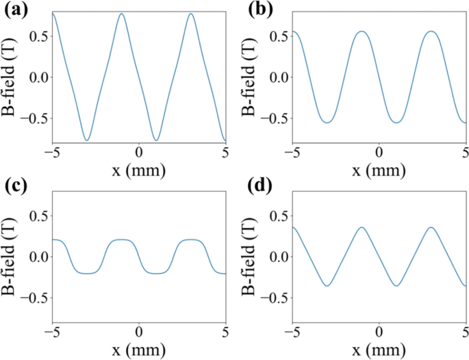
Additionally, it is worth to noting that adjusting magnet configurations or pole shapes can manipulate the field generated by the magnet array [40, 43]. This approach may significantly reduce the number of transverse wigglers needed to generate complex correlations. For instance, changing the width ratio of magnets with vertical and horizontal polarizations in \(N=4\) Halbach array alters the sharpness of the peaks in cosines, as shown in Fig. 13 a–c. Similarly, adding a sharp tip also sharpens the peaks and transforms the cosine into triangular shapes. Generating these adjusted modulations would typically require the superposition of 5–10 normal transverse wigglers.
Simulated magnetic field with various magnet configuration and geometry. a–c correspond to different width ratios of vertically and horizontally polarized magnets. b corresponds to a standard Halbach array. d shows the result with sharp tips attached to the vertically polarized magnets. Figure is from Ref. [43]
Since the research on arbitrary correlation using transverse wiggler is relatively new, it still faces several challenges to address [39]. For examples, there is a vertical dependency on the field strength (see Eq. 9, which can lead to strong x-y coupling and increase the emittance. Also, the transverse wiggler generates both vertical and horizontal magnetic fields along x-direction. This results in unwanted x-dependent kicks in the beam’s vertical phase space, which potentially deteriorates beam quality. Additionally, while particles’ positions are effectively frozen in the longitudinal phase space due to the relativistic effects, transverse positions are not. Therefore, the thickness of transverse wiggler, the number of transverse wigglers, and their longitudinal separations must be carefully considered during design and tuning.
4.3 Approaches to impart arbitrary correlations in longitudinal phase space using transverse wigglers
While transverse wigglers can impart arbitrary correlations, their effects are limited to updating transverse momentums. Therefore, applying the same concept to generate arbitrary longitudinal correlations may require implementing a series of wakefied structures or despite their inherent limitations. However, two approaches could potentially resolve this limitation and enable transverse wigglers to impart arbitrary correlations on the longitudinal phase space.
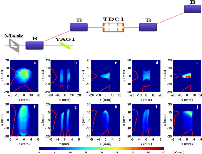
The first approach is to utilize emittance exchange (EEX) [8, 9, 44]. EEX is a specialized manipulation technique that directly controls the density distribution. This method uses two identical doglegs with a TDC in the middle to exchange one of transverse phase spaces with the longitudinal phase space (see Fig. 14). As a result, any upstream transverse properties can be transferred to the longitudinal phase space through the EEX beamline. EEX was experimentally demonstrated in 2011 [45]. Later, more generalized transfers of transverse properties and longitudinal controls were demonstrated [46, 47]. Similar to the demonstration of density profile shaping shown in Fig. 14, any transverse correlations generated by transverse wigglers will become longitudinal correlations after passing through the EEX beamline.
Emittance exchange beamline and experimental demonstration of bunch shaping. The top figure shows an emittance exchange beamline using two identical doglegs. a–e display experimentally measured x-y distribution of the beam updstream of the emittance exchange beamline. f–j show the corresponding z-x distribution downstream. Figures are adapted from Ref. [48]
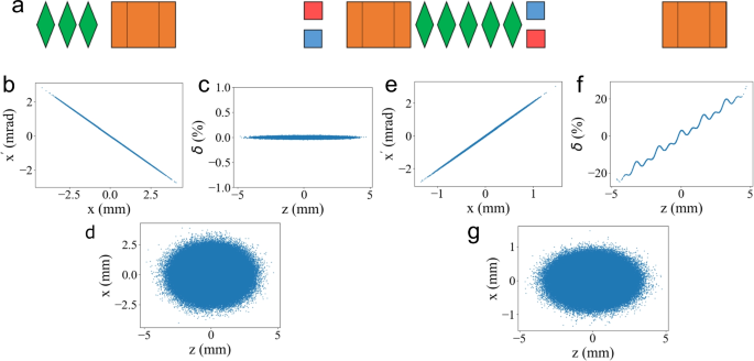
The second approach involves coupling between the x- and z-coordinates using a TDC, as shown in Fig. 15. The first TDC creates x-z coupling, which makes the particles’ x-coordinates at the transverse wiggler location determined by both initial beam size and bunch length. Quadrupoles placed before the first TDC can minimize the contribution of initial beam size. Then, the wiggler can impart modulations on z-x’ phase space. After a short drift, x’ updates x, and the beam enters the second TDC, which provides acceleration or deceleration based on particles’ x-positions. Consequently, z-\(\delta\) correlation forms. In this way, transverse wiggler can impart arbitrary correlations on the longitudinal phase space. However, this process also leaves unwanted modulations in the x-x’ phase space. To address this, a reverse drift section is built using five quadrupoles to eliminate shear in the phase space. Then, another set of transverse wigglers, configured to be the exact opposite of the modulator, eliminates the modulation in the x phase space. The remaining z-x coupling can be eliminated by the third TDC.
Simulations for a deflecting cavity-based beamline for longitudinal arbitrary correlations. a shows the beamline with green diamonds representing quadrupole magnets, orange boxes indicating TDCs, and red-blue pairs denoting transverse wigglers. b–d display the beam’s phase spaces before correlation manipulation. e–g show the phase spaces after the manipulation. Figures are adapted from Ref. [48]
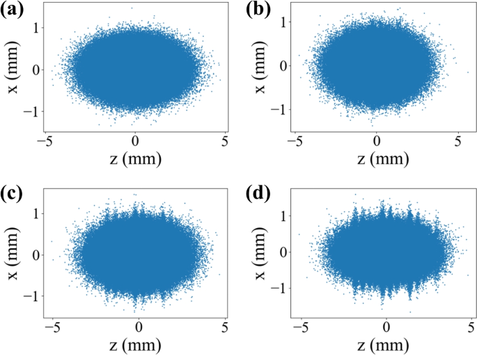
The simulation result shown in Fig. 15 clearly demonstrates the feasibility of the beamline. However, the design requires numerous elements and involves complex tuning due to the reverse drift. Additionally, any imperfections in the modulation removal process may lead to significant emittance growth in x-plane. Figure 16 shows the final z-x phase space of the beam with varying initial horizontal emittances. A large emittance introduces imperfections during the correlation removal at the second transverse wigglers. It leaves coupling between transverse and longitudinal phase spaces as shown in panels b–d.
Impact of horizontal emittance in TDC-based system. a–d show the beam’s z-x distributions after the longitudinal correlation control. Each corresponds to increasing initial horizontal emittances from low to high. Figure is from Ref. [48]
5 Opportunities enabled by high-complexity nonlinearity control
Compared to existing polynomial-based correlations, the summation of cosines can generate a wider range of correlations as described in the previous section. This section discusses three intriguing new opportunities enabled by this advanced correlation control.
5.1 Density profile shaping without loss
Wakefield accelerators utilize the wakefield generated by bunches to produce accelerating gradients 100–1000 times higher than conventional accelerators. One of the key figures of merit for these accelerators is the acceleration efficiency, which can be defined as \(\eta \mathcal {E}_{drive}R\). \(\eta \mathcal {E}\) represents how much of drive bunch’s energy will be spent to generate the wakefield. R is the transformer ratio indicating main beam’s energy gain per unit energy loss of the drive beam [33]. The transformer ratio is typically limited to 2 by the fundamental theorem of wakefield, but it can be enhanced by breaking the symmetry of the beam’s longitudinal density profile [21].
Various methods have been proposed to shape longitudinal profiles, but each comes with limitations [49]. The methods can be broadly divided into mask-based and correlation-based approaches. Mask-based shaping offers high precision but incurs significant particle losses (50–80%) [46, 50, 51]. On the other hand, correlation-based methods are lossless but either provide low shaping quality or are limited to simpler profiles like a single triangle due to challenges in handling complex nonlinearity [27, 30, 52, 53].
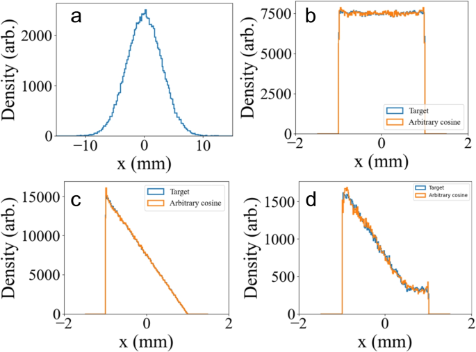
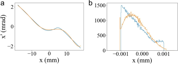
Recent simulations in Refs. [39, 40] demonstrated the feasibility of generating arbitrary density profile through transverse wiggler-based correlation control. While this approach is also correlation-based, its shaping capability and quality were significantly enhanced. Notably, Ref. [40] showcased the generation of a doorstep profile for the first time using this method in simulations.
When the target profile and the beamline are known, charge conservation provides a simple relationship between upstream and downstream distributions as below [40],
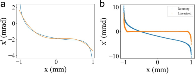
where \(R_{ij}\) are elements of the transfer matrix, N(x) are the initial and final density profiles, and F is the correlation. Solving this equation yields the desired correlation. It is worth to emphasize that the correlations for each profile in Fig. 17 were approximated using 4, 5, and 7 transverse wigglers. However, the correlation required for the doorstep profile cannot be generated by either a 12th-order polynomial or a 20-order polynomial. Figure 18 shows the approximation of a correlation for the doorstep profile using polynomial series and its corresponding density profile. Panel a highlights clear differences between the desired correlation and the polynomial approximation. This leads to significant discrepancies in the final density profiles as shown in panel b.
Simulation results of transverse wiggler-based shaping. a shows initial density profile. b–d show final density profiles. Blue curves represent desired profiles while orange curves are generated by the wiggler-based method. Figure is adapted from Ref. [40]
5.2 Sawtooth correlation for optimal bunching
As described in earlier sections, bunch trains are a great source of coherent radiation [54]. There are several methods to form bunch trains, one of which involves imparting sinusoidal modulations. When the modulated beam passes through a chicane or drift, particles start to move and arrive at the zero-crossing points around the same time due to the momentum differences. Although sinusoidal modulations create intense density spikes, not all particles contribute to forming these spikes. Due to nonlinearity of the sine curve, only the particles experiencing linear modulation reach the zero-crossing point, while the others do not.
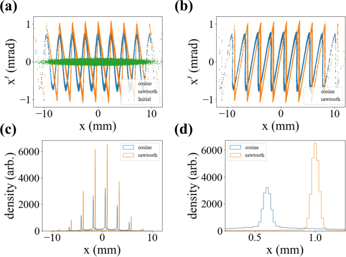
The most effective solution to enhance performance is to generate a sawtooth correlation instead of sine modulation. Sawtooth correlations present another instance where polynomials cannot provide an adequate approximation, which is why the sawtooth has been overlooked. However, sawtooth patterns can be easily generated by Fourier series. Figure 19 shows the results obtained with 10 transverse wigglers. Since the falling edge is not an hard edge, around 90% of particles experiences linear modulation and contribute to forming the spike. The peak density increases more than a factor of two. Currently, the performance is limited by Gibbs phenomena. It could be further improved by applying a Lancoz factor or increasing the number of harmonics.
Comparison of sine and sawtooth modulations in simulation. a shows phase space before modulation (green), after sinusoidal modulation (blue), and after sawtooth modulation (orange). b shows the corresponding phase space after a drift that maximizes the peak charge density. c and d compare the final horizontal density modulations
5.3 Linearization of complex nonlinearity
Another significant application of advanced nonlinearity control is linearization. For instance, the phase space after generating a doorstep profile exhibits high nonlinearity. If the beam undergoes additional propagation through a drift or chicane, this remaining correlation can alter the density profile. Therefore, linearizing this residual correlation is crucial. Similar to the shaping process, this remaining correlation cannot be approximated using polynomials. However, 10 wigglers can successfully linearize this correlation as shown in Fig. 20.
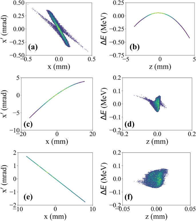
This advanced linearization capability can be utilized to generate high-brightness beams. Reference [55] proposed an EEX-based photoinjector. In most photoinjectors, transverse emittance is significantly smaller than longitudinal emittance. Two main reasons for the high longitudinal emittance are (1) strong nonlinearity and (2) large momentum spread at the periphery of the beam. Reference [55] proposed exchanging the transverse and longitudinal phase space, which provides several advantages for longitudinal control. These include compression, chirp control, shaping, and potentially avoiding microbunching instability. The original longitudinal phase space is then linearized using transverse wigglers, and the periphery is removed by a wide slit.
As summarized in Fig. 21, the start-to-end simulation demonstrated promising results achieving transverse and longitudinal emittances of 0.63 \(\mu m\) and 0.44 \(\mu m\), respectively. The bunch length after the EEX injector was 6.9 microns, and the energy spread was 32 keV. These metrics are comparable to or better than those observed downstream of X-ray free electron laser facilities, which are typically killometer-long (EEX injector is about 15 m). Successful experimental validation in the future would open new opportunities for enhanced control over longitudinal phase space, performance improvements, and significant cost savings. The implementation of this injector could enable (a) operating all linac on-crest, (2) eliminating the need for harmonic cavities and RF sources, (3) removing the need for compressors and dechirpers, and (4) possibly removing laser heater.
Start-to-end simulations results of EEX photoinjector. Each row shows phase spaces at three different stages: the exit of the linac (a, b), at the exit of the EEX beamline (c, d), and afer the linearization by transverse wigglers and pheriphery cut (e, f), respectively. Figure is adapted from Ref. [55]
6 Conclusion
We have reviewed several conventional methods that control low-complexity nonlinearities and a new approach toward high-complexity nonlinearites. There is no doubt that the conventional methods have been effective and have provided significant advancements in accelerator systems and applications. However, the correlations that conventional methods can generate are strictly limited to low-order polynomials or the summation of 1–2 sine modulations. On the other hand, the summation of cosines can generate all correlations that polynomials can generate and beyond. Fourier approximation can handle periodic correlations while nonperiodic ones can be well approximated by an arbitrary cosine sum. A tool called the transverse wiggler was introduced to impart designed cosine modulations, and its applications have been discussed. These applications have all demonstrated the feasibility of newly enabled opportunities.
This research area is still in the early stages. It requires more support and effort to further develop methods, tools, and applications. More detailed studies on limiting factors and side effects will be necessary. Ultimately, this research must be extended to higher dimensions. Along with recent efforts to diagnose high-dimensional beam characteristics [56,57,58], efforts toward high-dimensional control would provide a path toward next major advancement of modern accelerators.
Data availability
Not applicable.
References
-
E.O. Lawrence, M.S. Livingston, The production of high speed light ions without the use of high voltages. Phys. Rev. 40, 19–35 (1932). https://doi.org/10.1103/PhysRev.40.19
-
E.D. Courant, M.S. Livingston, H.S. Snyder, The strong-focusing synchroton–a new high energy accelerator. Phys. Rev. 88, 1190–1196 (1952). https://doi.org/10.1103/PhysRev.88.1190
-
S. Shin, New era of synchrotron radiation: fourth-generation storage ring. AAPPS Bull. 31(1), 21 (2021). https://doi.org/10.1007/s43673-021-00021-4
-
K.J. Kim, Z. Huang, R. Lindberg, Synchrotron Radiation and Free-Electron Lasers: Principles of Coherent X-ray Generation (Cambridge University Press, Cambridge, 2017)
-
V.V. Parkhomchuk, A.N. Skrinsky, Cooling methods for charged particle beams. Rev. Accel. Sci. Technol. 01(01), 237–257 (2008). https://doi.org/10.1142/S1793626808000150
-
K.J. Kim, Round-to-flat transformation of angular-momentum-dominated beams. Phys. Rev. ST Accel. Beams 6, 104002 (2003). https://doi.org/10.1103/PhysRevSTAB.6.104002
-
B.E. Carlsten, K.A. Bishofberger, L.D. Duffy, S.J. Russell, R.D. Ryne, N.A. Yampolsky, A.J. Dragt, Arbitrary emittance partitioning between any two dimensions for electron beams. Phys. Rev. ST Accel. Beams 14, 050706 (2011). https://doi.org/10.1103/PhysRevSTAB.14.050706
-
M. Cornacchia, P. Emma, Transverse to longitudinal emittance exchange. Phys. Rev. ST Accel. Beams 5, 084001 (2002). https://doi.org/10.1103/PhysRevSTAB.5.084001
-
P. Emma, Z. Huang, K.J. Kim, P. Piot, Transverse-to-longitudinal emittance exchange to improve performance of high-gain free-electron lasers. Phys. Rev. ST Accel. Beams 9, 100702 (2006). https://doi.org/10.1103/PhysRevSTAB.9.100702
-
P. Franz, S. Li, T. Driver, R.R. Robles, D. Cesar, E. Isele, Z. Guo, J. Wang, J.P. Duris, K. Larsen, J.M. Glownia, X. Cheng, M.C. Hoffmann, X. Li, M.F. Lin, A. Kamalov, R. Obaid, A. Summers, N. Sudar, E. Thierstein, Z. Zhang, M.F. Kling, Z. Huang, J.P. Cryan, A. Marinelli, Terawatt-scale attosecond x-ray pulses from a cascaded superradiant free-electron laser. Nat. Photon. 18(7), 698–703 (2024). https://doi.org/10.1038/s41566-024-01427-w
-
V. Yakimenko, S. Meuren, F. Del Gaudio, C. Baumann, A. Fedotov, F. Fiuza, T. Grismayer, M.J. Hogan, A. Pukhov, L.O. Silva, G. White, Prospect of studying nonperturbative qed with beam-beam collisions. Phys. Rev. Lett. 122, 190404 (2019). https://doi.org/10.1103/PhysRevLett.122.190404
-
Q. Gao, G. Ha, C. Jing, S.P. Antipov, J.G. Power, M. Conde, W. Gai, H. Chen, J. Shi, E.E. Wisniewski, D.S. Doran, W. Liu, C.E. Whiteford, A. Zholents, P. Piot, S.S. Baturin, Observation of high transformer ratio of shaped bunch generated by an emittance-exchange beam line. Phys. Rev. Lett. 120, 114801 (2018). https://doi.org/10.1103/PhysRevLett.120.114801
-
R. Roussel, G. Andonian, W. Lynn, K. Sanwalka, R. Robles, C. Hansel, A. Deng, G. Lawler, J.B. Rosenzweig, G. Ha, J. Seok, J.G. Power, M. Conde, E. Wisniewski, D.S. Doran, C.E. Whiteford, Single shot characterization of high transformer ratio wakefields in nonlinear plasma acceleration. Phys. Rev. Lett. 124, 044802 (2020). https://doi.org/10.1103/PhysRevLett.124.044802
-
S. Nagaitsev, Z. Huang, J. Power, J.L. Vay, P. Piot, L. Spentzouris, J. Rosenzweig, Y. Cai, S. Cousineau, M. Conde, M. Hogan, A. Valishev, M. Minty, T. Zolkin, X. Huang, V. Shiltsev, J. Seeman, J. Byrd, Y. Hao, B. Dunham, B. Carlsten, A. Seryi, R. Patterson. Accelerator and beam physics research goals and opportunities (2021). Prepinrt at https://arxiv.org/abs/2101.04107. Accessed 26 July 2024
-
E. Hemsing, G. Stupakov, D. Xiang, A. Zholents, Beam by design: laser manipulation of electrons in modern accelerators. Rev. Mod. Phys. 86, 897–941 (2014). https://doi.org/10.1103/RevModPhys.86.897
-
G. Ha, K.J. Kim, J.G. Power, Y. Sun, P. Piot, Bunch shaping in electron linear accelerators. Rev. Mod. Phys. 94, 025006 (2022). https://doi.org/10.1103/RevModPhys.94.025006
-
H. Wiedemann, Particle Accelerator Physics (Springer, Berlin, 2015). https://doi.org/10.1007/978-3-319-18317-6
-
F. Meot, T. Aniel, Principles of the non-linear tuning of beam expanders. Nucl. Inst. Methods Phys. Res. Sect. A Accel. Spectrometers Detectors Assoc. Equip. 379(2), 196–205 (1996). https://doi.org/10.1016/0168-9002(96)00539-6
-
Y. Yuri, N. Miyawaki, T. Kamiya, W. Yokota, K. Arakawa, M. Fukuda, Uniformization of the transverse beam profile by means of nonlinear focusing method. Phys. Rev. ST Accel. Beams 10, 104001 (2007). https://doi.org/10.1103/PhysRevSTAB.10.104001
-
G. Ha, M. Chung, M. Conde, J. Power, J. Seok, in Proceeding of 3rd North American Particle Accelerator Conference, Lansing, USA, 2–6 September 2019. Applications and opportunities for the emittance exchange beamline (2019). https://doi.org/10.18429/JACoW-NAPAC2019-FRXBA3
-
K.L. Bane, P. Chen, P.B. Wilson, On collinear wake field acceleration. IEEE Trans. Nucl. Sci. 32, 3524–3526 (1985). https://doi.org/10.1109/TNS.1985.4334416
-
G. Loisch, G. Asova, P. Boonpornprasert, R. Brinkmann, Y. Chen, J. Engel, J. Good, M. Gross, F. Grüner, H. Huck, D. Kalantaryan, M. Krasilnikov, O. Lishilin, A.M. de la Ossa, T.J. Mehrling, D. Melkumyan, A. Oppelt, J. Osterhoff, H. Qian, Y. Renier, F. Stephan, C. Tenholt, V. Wohlfarth, Q. Zhao, Observation of high transformer ratio plasma wakefield acceleration. Phys. Rev. Lett. 121, 064801 (2018). https://doi.org/10.1103/PhysRevLett.121.064801
-
N. Yampolsky, E.I. Simakov, A. Malyzhenkov, Imposing strong correlated energy spread on relativistic bunches with transverse deflecting cavities. Phys. Rev. Accel. Beams 23, 054403 (2020). https://doi.org/10.1103/PhysRevAccelBeams.23.054403
-
J. Power, M. Conde, W. Gai, Z. Li, D. Mihalcea, in Proceedings of 1st International Particle Accelerator Conference, Tokyo, Japan, 23–28 May 2010. Upgrade of the drive LINAC for the AWA facility dielectric two-beam accelerator (JACoW, Geneva, 2010)
-
M.E. Conde, W. Gai, R. Konecny, Z.M. Yusof, W. Liu, J.G. Power, C.J. Jing, P. Piot, D. Mihalcea, M.M. Rihaoui, in Proceedings of International Particle Accelerator Conference 2012, New Orleans, USA, 20–25 May 2012. Commissioning of a 1.3-GHz deflecting cavity for phase-space exchange at the Argonne wakefield accelerator (JACoW, Geneva, 2012)
-
P. Emma, X-band RF harmonic compensation for linear bunch compression in the LCLS (SLAC, Menlo Park, 2001). SLAC-TN-05-004
-
P. Piot, C. Behrens, C. Gerth, M. Dohlus, F. Lemery, D. Mihalcea, P. Stoltz, M. Vogt, Generation and characterization of electron bunches with ramped current profiles in a dual-frequency superconducting linear accelerator. Phys. Rev. Lett. 108, 034801 (2012). https://doi.org/10.1103/PhysRevLett.108.034801
-
T.P. Wangler, RF Linear Accelerators (Wiley-VCH, Weinheim, 2008)
-
C. Jing, Dielectric wakefield accelerators. Rev. Accel. Sci. Technol. 09, 127–149 (2016). https://doi.org/10.1142/S1793626816300061
-
G. Andonian, S. Barber, F.H. O’Shea, M. Fedurin, K. Kusche, C. Swinson, J.B. Rosenzweig, Generation of ramped current profiles in relativistic electron beams using wakefields in dielectric structures. Phys. Rev. Lett. 118, 054802 (2017). https://doi.org/10.1103/PhysRevLett.118.054802
-
H. Deng, M. Zhang, C. Feng, T. Zhang, X. Wang, T. Lan, L. Feng, W. Zhang, X. Liu, H. Yao, L. Shen, B. Li, J. Zhang, X. Li, W. Fang, D. Wang, M.E. Couprie, G. Lin, B. Liu, Q. Gu, D. Wang, Z. Zhao, Experimental demonstration of longitudinal beam phase-space linearizer in a free-electron laser facility by corrugated structures. Phys. Rev. Lett. 113, 254802 (2014). https://doi.org/10.1103/PhysRevLett.113.254802
-
S. Antipov, M. Babzien, C. Jing, M. Fedurin, W. Gai, A. Kanareykin, K. Kusche, V. Yakimenko, A. Zholents, Subpicosecond bunch train production for a tunable mj level thz source. Phys. Rev. Lett. 111, 134802 (2013). https://doi.org/10.1103/PhysRevLett.111.134802
-
C. Jing, G. Ha, Roadmap for Structure-based Wakefield Accelerator (SWFA) R &D and its challenges in beam dynamics. JINST 17(05), T05007 (2022). https://doi.org/10.1088/1748-0221/17/05/T05007
-
R.B. PALMER, in Frontiers of Particle Beams, ed. by M. Month, S. Turner. An introduction to acceleration mechanisms (Springer Berlin Heidelberg, Berlin, 1988), pp. 607–635
-
K. Halbach, Physical and optical properties of rare earth cobalt magnets. Nucl. Inst. Methods Phys. Res. 187(1), 109–117 (1981). https://doi.org/10.1016/0029-554X(81)90477-8
-
E. Saldin, E. Schneidmiller, M. Yurkov, Longitudinal space charge-driven microbunching instability in the tesla test facility linac. Nucl. Inst. Methods Phys. Res. Sect. A Accel. Spectrometers Detectors Assoc. Equip. 528(1), 355–359 (2004). https://doi.org/10.1016/j.nima.2004.04.067. Proceedings of the 25th International Free Electron Laser Conference, and the 10th FEL Users Workshop
-
D. Cesar, A. Anakru, S. Carbajo, J. Duris, P. Franz, S. Li, N. Sudar, Z. Zhang, A. Marinelli, Electron beam shaping via laser heater temporal shaping. Phys. Rev. Accel. Beams 24, 110703 (2021). https://doi.org/10.1103/PhysRevAccelBeams.24.110703
-
G. Stupakov, Using the beam-echo effect for generation of short-wavelength radiation. Phys. Rev. Lett. 102, 074801 (2009). https://doi.org/10.1103/PhysRevLett.102.074801
-
G. Ha, M. Conde, J. Power, in Proceedings of 3rd North American Particle Accelerator Conference (NAPAC2019), Lansing, USA, 2–6 September 2019. Arbitrary transverse profile shaping using transverse wigglers (2019). https://doi.org/10.18429/JACoW-NAPAC2019-TUPLM15
-
G. Ha, in Proceedings of 14th International Particle Accelerator Conference, Venice, Italy, 7–12 May 2023. Arbitrary transverse and longitudinal correlation generation using transverse wiggler and wakefield structures (2023). https://doi.org/10.18429/JACoW-IPAC2023-WEPA045
-
G. Ha, M. Conde, J. Power, J. Shao, E. Wisniewski. in Proceedings of 10th International Particle Accelerator Conference, Melbourne, Australia, 19–24 May 2019. Tunable bunch train generation using emittance exchange beamline with transverse wiggler (2019). https://doi.org/10.18429/JACoW-IPAC2019-TUPGW089
-
G. Ha, D. Doran, E. Wisniewski, G. Andonian, J. Rosenzweig, J. Power, N. Majernik, W. Liu, in Proceedings of 15th International Particle Accelerator Conference, Nashville, USA, 19–24 May 2024. The reconfiggler: a uniquely versatile wiggler (JACoW, Geneva, 2024)
-
G. Ha, N. Majernik, in Proceedings of 15th International Particle Accelerator Conference, Nashville, USA, 19–24 May 2024. Generation of sawtooth correlation for bunching factor enhancement (2024). https://doi.org/10.18429/JACoW-IPAC2024-MOPG38
-
G. Ha, M.H. Cho, W. Gai, K.J. Kim, W. Namkung, J.G. Power, Perturbation-minimized triangular bunch for high-transformer ratio using a double dogleg emittance exchange beam line. Phys. Rev. Accel. Beams 19, 121301 (2016). https://doi.org/10.1103/PhysRevAccelBeams.19.121301
-
J. Ruan, A.S. Johnson, A.H. Lumpkin, R. Thurman-Keup, H. Edwards, R.P. Fliller, T.W. Koeth, Y.E. Sun, First observation of the exchange of transverse and longitudinal emittances. Phys. Rev. Lett. 106, 244801 (2011). https://doi.org/10.1103/PhysRevLett.106.244801
-
G. Ha, M.H. Cho, W. Namkung, J.G. Power, D.S. Doran, E.E. Wisniewski, M. Conde, W. Gai, W. Liu, C. Whiteford, Q. Gao, K.J. Kim, A. Zholents, Y.E. Sun, C. Jing, P. Piot, Precision control of the electron longitudinal bunch shape using an emittance-exchange beam line. Phys. Rev. Lett. 118, 104801 (2017). https://doi.org/10.1103/PhysRevLett.118.104801
-
J. Seok, G. Ha, J. Power, M. Conde, E. Wisniewski, W. Liu, S. Doran, C. Whiteford, M. Chung, Experimental demonstration of double emittance exchange toward arbitrary longitudinal beam phase-space manipulations. Phys. Rev. Lett. 129, 224801 (2022). https://doi.org/10.1103/PhysRevLett.129.224801
-
G. Ha, in Proceedings of 15th International Particle Accelerator Conference, Nashville, USA, 19–24 May 2024. Imparting arbitrary correlation on longitudinal phase space using transverse wigglers and deflecting cavities (2024). https://doi.org/10.18429/JACoW-IPAC2024-MOPS56
-
F. Lemery, G. Andonian, S. Doebert, G. Ha, X. Lu, J. Power, E. Wisniewski, Drive beam sources and longitudinal shaping techniques for beam driven accelerators. J. Instrum. 17(05), P05036 (2022). https://doi.org/10.1088/1748-0221/17/05/P05036
-
G. Ha, J.G. Power, J. Shao, M. Conde, C. Jing, Coherent synchrotron radiation free longitudinal bunch shaping using transverse deflecting cavities. Phys. Rev. Accel. Beams 23, 072803 (2020). https://doi.org/10.1103/PhysRevAccelBeams.23.072803
-
P. Muggli, B. Allen, V.E. Yakimenko, J. Park, M. Babzien, K.P. Kusche, W.D. Kimura, Simple method for generating adjustable trains of picosecond electron bunches. Phys. Rev. ST Accel. Beams 13, 052803 (2010). https://doi.org/10.1103/PhysRevSTAB.13.052803
-
R.J. England, J.B. Rosenzweig, G. Travish, Generation and measurement of relativistic electron bunches characterized by a linearly ramped current profile. Phys. Rev. Lett. 100, 214802 (2008). https://doi.org/10.1103/PhysRevLett.100.214802
-
Z. Song, S. Zhou, J. Hua, Y. Du, F. Li, B. Peng, W. Lu, Z. Wang, Coherent-synchrotron-radiation-free longitudinal shaping of a high-charge electron bunch based on velocity modulation. Phys. Rev. Accel. Beams 27, 092801 (2024). https://doi.org/10.1103/PhysRevAccelBeams.27.092801
-
A. Gover, R. Ianconescu, A. Friedman, C. Emma, N. Sudar, P. Musumeci, C. Pellegrini, Superradiant and stimulated-superradiant emission of bunched electron beams. Rev. Mod. Phys. 91, 035003 (2019). https://doi.org/10.1103/RevModPhys.91.035003
-
G. Ha, in Proceedings of 14th International Particle Accelerator Conference, Venice, Italy, 7–12 May 2023. Emittance exchange with periphery cut for high-brightness beam (2023). https://doi.org/10.18429/JACoW-IPAC2023-WEPA046
-
B. Cathey, S. Cousineau, A. Aleksandrov, A. Zhukov, First six dimensional phase space measurement of an accelerator beam. Phys. Rev. Lett. 121, 064804 (2018). https://doi.org/10.1103/PhysRevLett.121.064804
-
R. Roussel, A. Edelen, C. Mayes, D. Ratner, J.P. Gonzalez-Aguilera, S. Kim, E. Wisniewski, J. Power, Phase space reconstruction from accelerator beam measurements using neural networks and differentiable simulations. Phys. Rev. Lett. 130, 145001 (2023). https://doi.org/10.1103/PhysRevLett.130.145001
-
R. Roussel, J.P. Gonzalez-Aguilera, E. Wisniewski, A. Ody, W. Liu, J. Power, Y.K. Kim, A. Edelen, Efficient six-dimensional phase space reconstructions from experimental measurements using generative machine learning. Phys. Rev. Accel. Beams 27, 094601 (2024). https://doi.org/10.1103/PhysRevAccelBeams.27.094601
Acknowledgements
Not applicable.
Funding
Not applicable.
Author information
Authors and Affiliations
Contributions
The author proposed, collected, and reviewed the contents.
Corresponding author
Ethics declarations
Competing interests
The author declares no competing interests.
Additional information
Publisher’s Note
Springer Nature remains neutral with regard to jurisdictional claims in published maps and institutional affiliations.


