1 Introduction
High-precision clock synchronization has been an indispensable technology in numerous fields such as navigation [1], geodesy [2], astronomy [3], long baseline interferometry [4, 5], and communication [6,7,8,9]. Quantum clock synchronization (QCS) can measure out the high-precision clock difference among distant users, which breaks through the standard quantum limit by employing the properties of quantum entanglement. Currently, the QCS schemes that have been successfully verified include two-way QCS [10,11,12,13], Hong-Ou-Mandel (HOM) interferometer-based QCS [14], and round-trip QCS [15, 16]. In 2023, Tang et al. proposed a QCS network scheme using wavelength division multiplexing (WDM) with a magnesium oxide-doped periodically poled lithium niobate (MgO: PPLN) crystal spontaneous parametric down-conversion (SPDC) entangled photon source, where the number of wavelength channels to be occupied is 2m for m users [15]. The pair of entangled wavelength channels generated by SPDC [17] can only provide clock measurements between a single user and the server, this scheme faces difficulties such as excessive wavelength channel consumption and complex cabling.
Four-wave mixing (FWM) can also be used to fabricate entangled photon sources, which can use multiple beams of pump light of different wavelengths to achieve wavelength multicasting [18, 19]. The wavelength channels of entangled photon pairs generated by the SPDC effect are one-to-one relationships, but the wavelength multicasting through the multi-pump FWM effect can establish the entanglement relationship between a signal photons wavelength channel and multiple idler photons wavelength channels. In addition, wavelength multicasting of FWM is similar to wavelength conversion, which can be used for networking through WDM [18, 20] and decreases the wavelength channel consumption and the cabling complexity when applied to quantum computing, quantum communication, QCS, etc. [15, 21,22,23,24,25].
In this paper, we propose a more efficient QCS network scheme with the wavelength multicasting entangled photon source, which can decrease at least 25% of wavelength channel consumption compared with the scheme proposed by Tang et al. [15] under the same network scale. Afterwards, the four node QCS network is demonstrated, where the wavelength multicasting entangled photon source utilize with dual-pumped FWM silicon chip. The demonstration lasted for 11.1 h. The fiber of 10 km connection is between Alice and Charlie server, and 25 km fiber connection is between Bob and server. The time deviation (TDEV) between the server and each user (Alice, Bob, and Charlie) at an average time of 640 s is 3.43 ps, 2.03 ps, and 2.44 ps, respectively. Furthermore, the wavelength multicasting QCS network provides the foundation for the construction of larger-scale QCS networks, which are anticipated to play a pivotal role in future quantum networks.
2 Wavelength multicasting entangled photon source
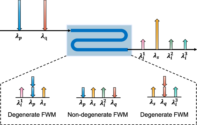
FWM is a nonlinear optical phenomenon that obeys the law of conservation of energy. In the phenomenon, two pump photons with wavelength \(\lambda _p\) and \(\lambda _q\) annihilate to generate a pair of signal and idler photons with wavelength \(\lambda _s\) and \(\lambda _i\), that is \(\lambda _p + \lambda _q = \lambda _s + \lambda _i\) [26,27,28]. FWM facilitates the energy conversion from one wavelength to another, known as the wavelength conversion [29], or to several wavelengths, known as the wavelength multicasting [30]. We utilize dual-pumped FWM to prepare a wavelength multicasting entangled photon source. As shown in Fig. 1, the pump photons (\(\lambda _{p}\) and \(\lambda _{q}\)) converted to signal photons (\(\lambda _{s}\)) and idler photons (\(\lambda _{q}^{1}\), \(\lambda _{q}^{2}\), and \(\lambda _{q}^{3}\)), under the action of degenerate and non-degenerate FWM. Once \(\lambda _s\) is selected as the wavelength channel of the signal photon, according to the law of energy conservation, there are three idler photon channels entangled with it, with wavelength of \(\lambda _{i}^{1}\) (\(\lambda _{p} + \lambda _{p} - \lambda _{s}\)), \(\lambda _{i}^{2}\) (\(\lambda _{p} + \lambda _{q} - \lambda _{s}\)), and \(\lambda _{i}^{3}\) (\(\lambda _{q} + \lambda _{q} - \lambda _{s}\)), respectively. Multiple sets of wavelength multicasting entanglement can be chosen to build a QCS network according to the scale of the network. This method provides a scalable and adaptable architecture for the needs of multi-node networking. Furthermore, according to the calculation, the number of idler photon channels entangled with a signal photon channel is \(s + \left( {\begin{array}{c}s\\ 2\end{array}}\right) = \frac{s(s+1)}{2}\), when the number of pump lights with different wavelengths is s.
Dual-pumped FWM wavelength multicasting entangled photon source. Under the action of degenerate and non-degenerate FWM, the pump photons (\(\lambda _{p}\) and \(\lambda _{q}\)) converted to signal photons (\(\lambda _{s}\)) and idler photons (\(\lambda _{q}^{1}\), \(\lambda _{q}^{2}\), and \(\lambda _{q}^{3}\))
3 QCS network scheme
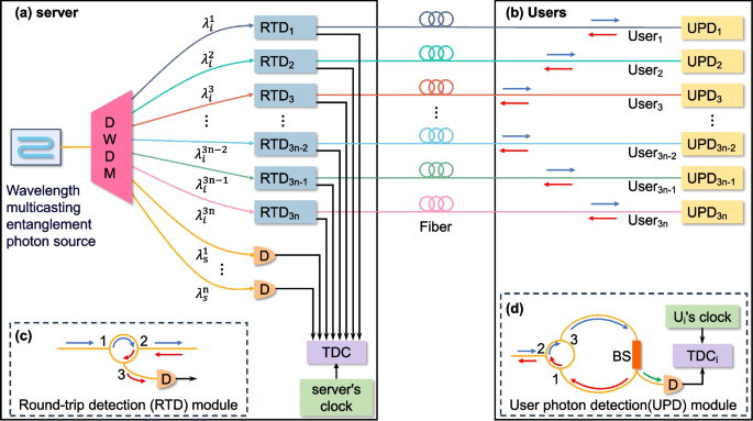
Take the double-pump FWM as an example, the proposed wavelength multicasting round-trip QCS network scheme is shown in Fig. 2. The entangled photons generated by the wavelength multicasting entanglement photon source are demultiplexed into photons with wavelengths \(\lambda _{i}^{j}\) (idler) and \(\lambda _{s}^{k}\) (signal), \(j\in [1,3n], k\in [1,n], n \in N^{*}\) by a dense wavelength-division multiplexing (DWDM).
Schematic diagram of a multi-user round-trip QCS scheme based on wavelength multicasting entanglement photon source. a The entangled photon pairs are demultiplexed by DWDM. The idler photons are then transmitted to the user after passing through a round-trip detection (RTD) module. The signal photons are transmitted to a detector for detection. b After the photons transmitted from the server to the user enter a user photon detection (UPD) module, the detector detects a portion of the photons, while the other portion returns to the server. c RTD module: the input photons pass through an optical circulator (OC) from port 1 to port 2 and the round-trip photons are detected by a detector. d UPD module: the input photons pass through an OC (from port 2 to port 3) and a beam splitter (BS), with a portion being detected directly and another portion being sent back to the server through port 1 to port 2 of the OC. The server’s and user’s detectors are connected to their respective time-to-digital converters (TDC), which are synchronized by their local clocks
Here, we take the clock synchronization process between \(\text {User}_{1}\) and the server as an example for a detailed explanation. The signal photons with the wavelength of \(\lambda _{s}^{1}\) are separated from the DWDM and directly detected at the server. The idler photons with the wavelength of \(\lambda _{i}^{1}\) are sent into the round-trip detection module (\(\text {RTD}_{1}\)), pass through optical circulate (OC) (from port 1 to port 2), and a section of optical fiber to reach the user photon detection module (\(\text {UPD}_{1}\)), and are transmitted to BS from port 3 of OC. The photons are divided into two parts by beam splitter (BS). One part is directly detected, and one part enters from port 1 of OC, exits from port 2, and returns to the \(\text {RTD}_{1}\) of the server. The returned photons are transmitted from port 3 of OC and detected. The outputs of all detectors are connected to the time-to-digital converter (TDC) synchronized with their local clocks.
The entangled photon pairs produced by FWM are time-correlated [31,32,33]. The time difference between the signal-idler photon pairs measured at two space-time points \((r_{1},t_{1})\) and \((r_{2},t_{2})\) is given by the peak position of the second-order correlation function \(G^{(2)}\), which is derived from the joint distribution [34, 35].
where \(E^{(+)}\) and \(E^{(-)}\) are the positive-frequency and negative-frequency part of the electric field operators at space-time point \((r_{i},t_{i}),i=1,2.\) The time when the signal photons are detected is recorded as \(t_{1}\). The times at which the idler photons are detected by the \(\text {UPD}_{1}\) and returning to the \(\text {RTD}_{1}\) are recorded as \(t_1\) and \(t_2\), respectively. The time difference \(\tau _{s-u}\) between \(t_{1}\) and \(t_{2}\) consists of \(\Delta t_{s-u}\) (the time needed for the photons to reach \(\text {User}_{1}\) from the server) and the clock difference \(\Delta t_{1}\), which can be expressed as
The time difference \(\tau _{s-u-s}\) between \(t_1\) and \(t_3\) represents the whole round-trip propagation time \(\Delta t_{s-u-s}\) of the photons between the server and \(\text {User}_{1}\), which can be expressed as
Since the photons have the same round-trip propagation time between the server and \(\text {User}_{1}\), it can be derived that the clock difference is expressed as
The clock difference \(\Delta t_{a}\) between other users and the server can also be calculated using the method described above, where \(a\in [1,3n], n \in N^{*}\). The clock difference between any two users \(\text {User}_{a}\) and \(\text {User}_{b}\) can be expressed as
where \(a, b\in [1, 3n], n \in N^{*}\).
In the network scheme, the number of wavelength channels occupied is \(\left\lceil \frac{4m}{3} \right\rceil\) for m users, which can decrease the consumption of wavelength channels by at least 25% compared to the scheme proposed by Tang et al. [15], under the same network scale. Specifically, when equipped with 3m users, wavelength channel consumption is decreased by \(\frac{1}{3}\). This significant enhancement demonstrates the superiority and potential of our scheme in the QCS network.
4 Experimental setup
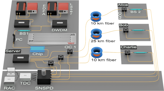
In the experiment, we set up a server and three users (Alice, Bob, and Charlie) to demonstrate the wavelength multicasting QCS network, shown in Fig. 3. The pump source is generated by two tunable lasers with center wavelengths of 1555.75 nm and 1544.53 nm, corresponding to International Telecommunication Union’s (ITU, 100 GHz) channels C27 and C41, respectively.
Experimental setup of round-trip multiple users (one server and three users) QCS based on wavelength multicasting entanglement photon source. EDFA, erbium-doped fiber amplifier; DWDM, dense wavelength division multiplexer; BS, beam splitter; PC, polarization controller; OC, optical circulator; SNSPD, superconducting nanowire single-photon detector; TDC, time-to-digital converters; RAC, rubidium atomic clock
Pump lights are amplified by erbium-doped fiber amplifiers (EDFA) respectively. The amplified spontaneous emission (ASE) noise and pump sideband noise are filtered out using a DWDM. Then, the two pump lights are combined into a beam of light by \(\text {BS}_{1}\). A polarization controller (PC) adjusts the pump light for polarization and then pairs it into a silicon waveguide through a grating coupler. At the other end of the waveguide, a DWDM is connected to filter out the residual pump light and demultiplex the generated signal-idler photon pairs. The signal photons correspond to ITU C33, centered at 1550.92 nm. The idler photons correspond to C21 (centered at 1560.61 nm), C35 (centered at 1549.32 nm), and C49 (centered at 1538.19 nm), respectively. The signal photons are detected by the superconducting nanowire single-photon detector (SNSPD) after exiting from the DWDM and are time-stamped by the TDC. The TDC’s clock is synchronized with the location’s clock. Alice and Charlie are connected to the server by 10 km fiber through C49 and C21, respectively. Bob is connected to the server by 25 km fiber through C35.
We take the clock synchronization between Alice and the server as an example to describe the experiment. Photons from C49 undergo DWDM demultiplexing and an \(\text {OC}_{1}\) and then travel over fiber of 10 km to \(\text {OC}_{2}\) and \(\text {BS}_{2}\), where they split into two parts. One part is transmitted to Alice for detection. The other part will return to the server by re-enter \(\text {OC}_{2}\) and the fiber of 10 km. The returned photons arrive at the server from port 3 of \(\text {OC}_{1}\) and are detected by the SNSPD. The outputs of SNSPD are connected to a TDC. Furthermore, the rubidium atomic clock (RAC) provides an accurate reference clock for the TDC [36], which serves to reduce the clock drift and jitter of the TDC, thereby enhancing the accuracy of the measurements.
5 Analysis of results
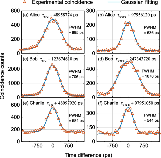
During the experiment, the time differences \(\tau _{s-u}\) and \(\tau _{s-u-s}\) were calculated at intervals of 20 s using the Eqs. (2) and (3) to ensure the accuracy of the results. The Gaussian fitting results for the first 20 s are shown in Fig. 4.
The coincidence count histograms of \(G^{(2)}(\tau _{s-u})\) and \(G^{(2)}(\tau _{s-u-s})\) in the first 20 s experiment. a and b show the coincidence histograms \(G^{(2)}(\tau _{s-u})\) and \(G^{(2)}(\tau _{s-u-s})\) of Alice, while (c and d) as well as (e and f) show the same for Bob and Charlie, respectively
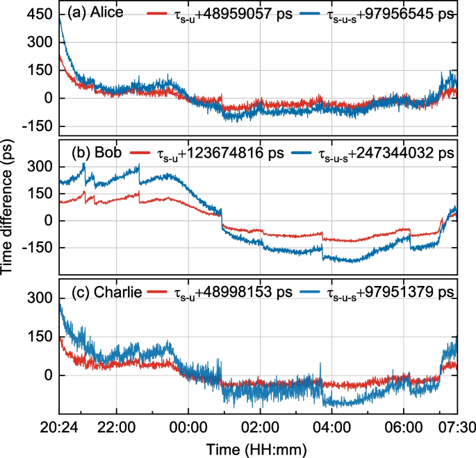
Due to the presence of group velocity dispersion in optical fibers, the full width at half maximum (FWHM) of \(G^{(2)}(\tau _{s-u-s})\) coincidence histogram belonging to Bob is greater than the FWHM of \(G^{(2)}(\tau _{s-u})\). However, Alice and Charlie exhibit completely different phenomena from those mentioned above. This is due to the different noise levels in the channels used by the users, leading to different photon counts. An increase in photon count exacerbates the time drift in SNSPD [37] and affects the extreme points and full width at FWHM of the coincidence counting histogram. The time differences \(\tau _{s-u}\) and \(\tau _{s-u-s}\) between the server and the users over consecutive 11.1 hours are shown in Fig. 5. The time differences \(\tau _{s-u}\) and \(\tau _{s-u-s}\) for each user are calculated from the fitting results. The \(\tau _{s-u}\) (\(\tau _{s-u-s}\)) expectations between the server and each user (Alice, Bob, and Charlie) are –48959057 ps (–97956545 ps), –123674816 ps (–247344032 ps), and –48998153 ps (–97951379 ps), respectively.
The fluctuations for Bob are less pronounced than those for other users within the same time, mainly due to two reasons: firstly, the degree of time drift of the SNSPD varies among them. Secondly, Bob’s Coincidences-to-Accidentals Ratio (CAR) is significantly higher than other users, contributing to more accurate and stable results during the Gaussian fitting process. Overall, time difference measurements are affected by noise. Furthermore, because of the intrinsic instability of the chip coupling platform, manual adjustments of the coupling efficiency may occasionally be required during the experiment to ensure the stability of the number of photon pairs generated. This results in a sudden change in the photon count for each channel, leading to abrupt variations in the time differences \(\tau _{s-u}\) and \(\tau _{s-u-s}\) (the extreme points of the Gaussian fitting of the coincidence count histogram), as illustrated in the Fig. 5. However, the variation in \(\tau _{s-u-s}\) for each user is about twice the variation in \(\tau _{s-u}\). Therefore, these variations tend to offset each other when calculating the clock difference.
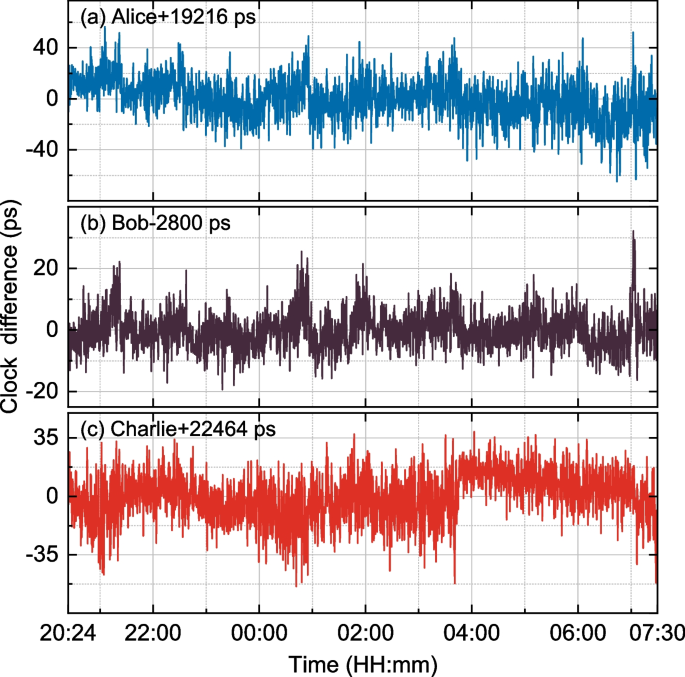
The clock difference \(\Delta t\) can be calculated according to Eq. (4), as shown in Fig. 6. The standard deviations of the clock difference between the server and each user (Alice, Bob, and Charlie) are 16.2006 ps, 6.2810 ps, and 14.6764 ps, respectively. The non-zero value of \(\Delta t\) can be attributed to the transmission time asymmetry of various system components (such as BS, OC, DWDM, and PC) and the time drift of the SNSPD [15].
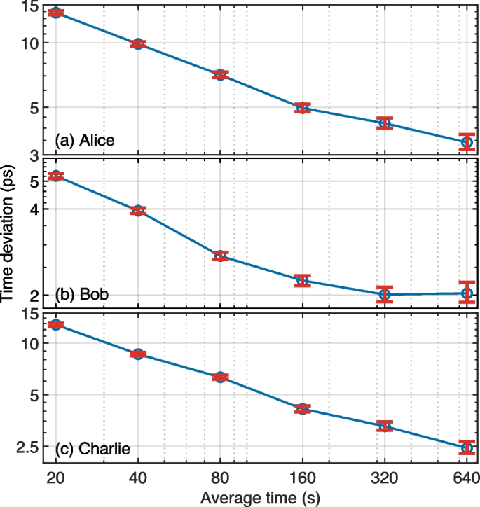
Figure 7 demonstrates the TDEV between the server and each user (Alice, Bob, and Charlie), which at an average time of 640 s is 3.43 ps, 2.03 ps, and 2.44 ps, respectively. The TDEV of Bob is superior to those of Alice and Charlie. Initially, the noise level of the wavelength channel utilized by Bob was lower than that of the other two users. Different noise levels lead to variations in both the CAR and photon count, resulting in more stable and accurate Gaussian fitting results. A stable and precise Gaussian fitting indicates a stable time difference, which in turn reduces fluctuations in the clock difference. Ultimately, smaller fluctuations in clock difference lead to a smaller TDEV calculation result. In conclusion, to achieve a lower TDEV, it is necessary to reduce the noise level and maintain an appropriate photon count, which can improve performance even over longer transmission distances.
6 Conclusion
In this paper, we propose a more efficient QCS network scheme with the wavelength multicasting entangled photon source, which can decrease at least 25% of wavelength channel consumption compared with the previous QCS network scheme under the same network scale. Afterwards, the four node QCS network is demonstrated, where the wavelength multicasting entangled photon source utilize with dual-pumped FWM silicon chip. The demonstration lasted for 11.1 h. The fiber of 10 km connection is between the Alice and Charlie server, and 25 km fiber connection is between Bob and server. The time deviation (TDEV) between the server and each user (Alice, Bob, and Charlie) at an average time of 640 s is 3.43 ps, 2.03 ps, and 2.44 ps respectively. In addition, the scale of wavelength multicasting can be expanded by adding pump lights of different wavelengths, so that one signal wavelength channel can be entangled with more idle optical wavelength channels, which further decreases the consumption of wavelength channel and flexibly adapts to more complex network environments. When the number of users is an integer multiple of the number of idler wavelength channels entangled with a signal wavelength channel, the wavelength channel saving will be maximized. Our scheme is expected to play a key role in future quantum networks, laying the foundation for achieving larger-scale QCS networks.


